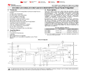
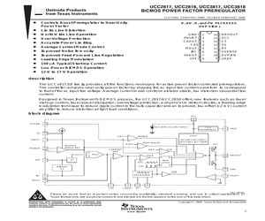
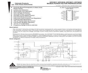
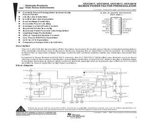
CU NIPDAU Level-1-260C-UNLIM 0 to 70 UCC3817D UCC3817DW ACTIVE SOIC DW 16 40 Green (RoHS & no Sb/Br) CU NIPDAU Level-2-260C-1 YEAR 0 to 70 UCC3817DW UCC3817DWTR ACTIVE SOIC DW 16 2000 Green (RoHS & no Sb/Br) CU NIPDAU Level-2-260C-1 YEAR 0 to 70 UCC3817DW UCC3817N ACTIVE PDIP N 16 25 Green (RoHS & no Sb/Br) CU NIPDAU N / A for Pkg Type 0 to 70 UCC3817N UCC3817NG4 ACTIVE PDIP N 16 25 Green (RoHS & no Sb/Br) CU NIPDAU N / A for Pkg Type 0 to 70 UCC3817N Addendum-Page 1 Samples PACKAGE OPTION ADDENDUM www.ti.com 24-Aug-2018 Orderable Device Status (1) Package Type Package Pins Package Drawing Qty Eco Plan Lead/Ball Finish MSL Peak Temp (2) (6) (3) Op Temp (C) Device Marking (4/5) UCC3818D ACTIVE SOIC D 16 40 Green (RoHS & no Sb/Br) CU NIPDAU Level-1-260C-UNLIM 0 to 70 UCC3818D UCC3818DTR ACTIVE SOIC D 16 2500 Green (RoHS & no Sb/Br) CU NIPDAU Level-1-260C-UNLIM 0 to 70 UCC3818D UCC3818DTRG4 ACTIVE SOIC D 16 2500 Green (RoHS & no Sb/Br) CU NIPDAU Level-1-260C-UN
 45 Pages, 2244 KB, Original
urn-on Threshold 10.2 V Turn-on Threshold 16 V Turn-on Threshold 10.2 V Turn-on Threshold 16 V Turn-on Threshold 10.2 V -40C to 85C UCC2817D UCC2818D UCC2817DW UCC2818DW UCC2817N UCC2818N UCC2817PW UCC2818PW 0C to 70C UCC3817D UCC3818D UCC3817DW UCC3818DW UCC3817N UCC3818N UCC3817PW UCC3818PW THERMAL RESISTANCE TABLE PACKAGE jc(C/W) ja(C/W) SOIC-16 (D) 22 SOIC-16 (DW) 26 40 to 70 (1) 89 to 102 (1) PDIP-16 (N) 12 14 (2) 25 to 50 (1) 123 to 147 (2) TSSOP-16 (PW) NOTES: (1) Specified ja (junction to ambient) is for devices mounted to 5-inch2 FR4 PC board with one ounce copper where noted. When resistance range is given, lower values are for 5 inch2 aluminum PC board. Test PWB was 0.062 inch thick and typically used 0.635-mm trace widths for power packages and 1.3-mm trace widths for non-power packages with a 100-mil x 100-mil probe land area at the end of each trace. (2). Modeled data. If value range given for ja, lower value is for 3x3 inch. 1 oz internal copper ground plane, higher value is for 1x
 28 Pages, 810 KB, Original
CU NIPDAU Level-1-260C-UNLIM 0 to 70 UCC3817D UCC3817DW ACTIVE SOIC DW 16 40 Green (RoHS & no Sb/Br) CU NIPDAU Level-2-260C-1 YEAR 0 to 70 UCC3817DW UCC3817DWTR ACTIVE SOIC DW 16 2000 Green (RoHS & no Sb/Br) CU NIPDAU Level-2-260C-1 YEAR 0 to 70 UCC3817DW UCC3817N ACTIVE PDIP N 16 25 Green (RoHS & no Sb/Br) CU NIPDAU N / A for Pkg Type 0 to 70 UCC3817N UCC3817NG4 ACTIVE PDIP N 16 25 Green (RoHS & no Sb/Br) CU NIPDAU N / A for Pkg Type 0 to 70 UCC3817N Addendum-Page 1 Samples PACKAGE OPTION ADDENDUM www.ti.com 24-Aug-2018 Orderable Device Status (1) Package Type Package Pins Package Drawing Qty Eco Plan Lead/Ball Finish MSL Peak Temp (2) (6) (3) Op Temp (C) Device Marking (4/5) UCC3818D ACTIVE SOIC D 16 40 Green (RoHS & no Sb/Br) CU NIPDAU Level-1-260C-UNLIM 0 to 70 UCC3818D UCC3818DTR ACTIVE SOIC D 16 2500 Green (RoHS & no Sb/Br) CU NIPDAU Level-1-260C-UNLIM 0 to 70 UCC3818D UCC3818DTRG4 ACTIVE SOIC D 16 2500 Green (RoHS & no Sb/Br) CU NIPDAU Level-1-260C-UN
 45 Pages, 2244 KB, Original
urn-on Threshold 10.2 V Turn-on Threshold 16 V Turn-on Threshold 10.2 V Turn-on Threshold 16 V Turn-on Threshold 10.2 V -40C to 85C UCC2817D UCC2818D UCC2817DW UCC2818DW UCC2817N UCC2818N UCC2817PW UCC2818PW 0C to 70C UCC3817D UCC3818D UCC3817DW UCC3818DW UCC3817N UCC3818N UCC3817PW UCC3818PW THERMAL RESISTANCE TABLE PACKAGE jc(C/W) ja(C/W) SOIC-16 (D) 22 SOIC-16 (DW) 26 40 to 70 (1) 89 to 102 (1) PDIP-16 (N) 12 14 (2) 25 to 50 (1) 123 to 147 (2) TSSOP-16 (PW) NOTES: (1) Specified ja (junction to ambient) is for devices mounted to 5-inch2 FR4 PC board with one ounce copper where noted. When resistance range is given, lower values are for 5 inch2 aluminum PC board. Test PWB was 0.062 inch thick and typically used 0.635-mm trace widths for power packages and 1.3-mm trace widths for non-power packages with a 100-mil x 100-mil probe land area at the end of each trace. (2). Modeled data. If value range given for ja, lower value is for 3x3 inch. 1 oz internal copper ground plane, higher value is for 1x
 31 Pages, 819 KB, Original
urn-on Threshold 10.2 V Turn-on Threshold 16 V Turn-on Threshold 10.2 V Turn-on Threshold 16 V Turn-on Threshold 10.2 V -40C to 85C UCC2817D UCC2818D UCC2817DW UCC2818DW UCC2817N UCC2818N UCC2817PW UCC2818PW 0C to 70C UCC3817D UCC3818D UCC3817DW UCC3818DW UCC3817N UCC3818N UCC3817PW UCC3818PW THERMAL RESISTANCE TABLE PACKAGE jc(C/W) ja(C/W) SOIC-16 (D) 22 SOIC-16 (DW) 26 40 to 70 (1) 89 to 102 (1) PDIP-16 (N) 12 14 (2) 25 to 50 (1) 123 to 147 (2) TSSOP-16 (PW) NOTES: (1) Specified ja (junction to ambient) is for devices mounted to 5-inch2 FR4 PC board with one ounce copper where noted. When resistance range is given, lower values are for 5 inch2 aluminum PC board. Test PWB was 0.062 inch thick and typically used 0.635-mm trace widths for power packages and 1.3-mm trace widths for non-power packages with a 100-mil x 100-mil probe land area at the end of each trace. (2). Modeled data. If value range given for ja, lower value is for 3x3 inch. 1 oz internal copper ground plane, higher value is for 1x
 27 Pages, 667 KB, Original
CU NIPDAU Level-1-260C-UNLIM 0 to 70 UCC3817D UCC3817DW ACTIVE SOIC DW 16 40 Green (RoHS & no Sb/Br) CU NIPDAU Level-2-260C-1 YEAR 0 to 70 UCC3817DW UCC3817DWTR ACTIVE SOIC DW 16 2000 Green (RoHS & no Sb/Br) CU NIPDAU Level-2-260C-1 YEAR 0 to 70 UCC3817DW UCC3817N ACTIVE PDIP N 16 25 Green (RoHS & no Sb/Br) CU NIPDAU N / A for Pkg Type 0 to 70 UCC3817N UCC3817NG4 ACTIVE PDIP N 16 25 Green (RoHS & no Sb/Br) CU NIPDAU N / A for Pkg Type 0 to 70 UCC3817N Addendum-Page 1 Samples PACKAGE OPTION ADDENDUM www.ti.com 24-Aug-2018 Orderable Device Status (1) Package Type Package Pins Package Drawing Qty Eco Plan Lead/Ball Finish MSL Peak Temp (2) (6) (3) Op Temp (C) Device Marking (4/5) UCC3818D ACTIVE SOIC D 16 40 Green (RoHS & no Sb/Br) CU NIPDAU Level-1-260C-UNLIM 0 to 70 UCC3818D UCC3818DTR ACTIVE SOIC D 16 2500 Green (RoHS & no Sb/Br) CU NIPDAU Level-1-260C-UNLIM 0 to 70 UCC3818D UCC3818DTRG4 ACTIVE SOIC D 16 2500 Green (RoHS & no Sb/Br) CU NIPDAU Level-1-260C-UN
 45 Pages, 2244 KB, Original
urn-on Threshold 10.2 V Turn-on Threshold 16 V Turn-on Threshold 10.2 V Turn-on Threshold 16 V Turn-on Threshold 10.2 V -40C to 85C UCC2817D UCC2818D UCC2817DW UCC2818DW UCC2817N UCC2818N UCC2817PW UCC2818PW 0C to 70C UCC3817D UCC3818D UCC3817DW UCC3818DW UCC3817N UCC3818N UCC3817PW UCC3818PW THERMAL RESISTANCE TABLE PACKAGE jc(C/W) ja(C/W) SOIC-16 (D) 22 SOIC-16 (DW) 26 40 to 70 (1) 89 to 102 (1) PDIP-16 (N) 12 14 (2) 25 to 50 (1) 123 to 147 (2) TSSOP-16 (PW) NOTES: (1) Specified ja (junction to ambient) is for devices mounted to 5-inch2 FR4 PC board with one ounce copper where noted. When resistance range is given, lower values are for 5 inch2 aluminum PC board. Test PWB was 0.062 inch thick and typically used 0.635-mm trace widths for power packages and 1.3-mm trace widths for non-power packages with a 100-mil x 100-mil probe land area at the end of each trace. (2). Modeled data. If value range given for ja, lower value is for 3x3 inch. 1 oz internal copper ground plane, higher value is for 1x
 31 Pages, 974 KB, Original
urn-on Threshold 10.2 V Turn-on Threshold 16 V Turn-on Threshold 10.2 V Turn-on Threshold 16 V Turn-on Threshold 10.2 V -40C to 85C UCC2817D UCC2818D UCC2817DW UCC2818DW UCC2817N UCC2818N UCC2817PW UCC2818PW 0C to 70C UCC3817D UCC3818D UCC3817DW UCC3818DW UCC3817N UCC3818N UCC3817PW UCC3818PW THERMAL RESISTANCE TABLE PACKAGE jc(C/W) ja(C/W) SOIC-16 (D) 22 SOIC-16 (DW) 26 40 to 70 (1) 89 to 102 (1) PDIP-16 (N) 12 14 (2) 25 to 50 (1) 123 to 147 (2) TSSOP-16 (PW) NOTES: (1) Specified ja (junction to ambient) is for devices mounted to 5-inch2 FR4 PC board with one ounce copper where noted. When resistance range is given, lower values are for 5 inch2 aluminum PC board. Test PWB was 0.062 inch thick and typically used 0.635-mm trace widths for power packages and 1.3-mm trace widths for non-power packages with a 100-mil x 100-mil probe land area at the end of each trace. (2). Modeled data. If value range given for ja, lower value is for 3x3 inch. 1 oz internal copper ground plane, higher value is for 1x
 27 Pages, 660 KB, Original
urn-on Threshold 10.2 V Turn-on Threshold 16 V Turn-on Threshold 10.2 V Turn-on Threshold 16 V Turn-on Threshold 10.2 V -40C to 85C UCC2817D UCC2818D UCC2817DW UCC2818DW UCC2817N UCC2818N UCC2817PW UCC2818PW 0C to 70C UCC3817D UCC3818D UCC3817DW UCC3818DW UCC3817N UCC3818N UCC3817PW UCC3818PW THERMAL RESISTANCE TABLE PACKAGE jc(C/W) ja(C/W) SOIC-16 (D) 22 SOIC-16 (DW) 26 40 to 70 (1) 89 to 102 (1) PDIP-16 (N) 12 14 (2) 25 to 50 (1) 123 to 147 (2) TSSOP-16 (PW) NOTES: (1) Specified ja (junction to ambient) is for devices mounted to 5-inch2 FR4 PC board with one ounce copper where noted. When resistance range is given, lower values are for 5 inch2 aluminum PC board. Test PWB was 0.062 inch thick and typically used 0.635-mm trace widths for power packages and 1.3-mm trace widths for non-power packages with a 100-mil x 100-mil probe land area at the end of each trace. (2). Modeled data. If value range given for ja, lower value is for 3x3 inch. 1 oz internal copper ground plane, higher value is for 1x
 25 Pages, 513 KB, Original
urn-on Threshold 10.2 V Turn-on Threshold 16 V Turn-on Threshold 10.2 V Turn-on Threshold 16 V Turn-on Threshold 10.2 V -40C to 85C UCC2817D UCC2818D UCC2817DW UCC2818DW UCC2817N UCC2818N UCC2817PW UCC2818PW 0C to 70C UCC3817D UCC3818D UCC3817DW UCC3818DW UCC3817N UCC3818N UCC3817PW UCC3818PW THERMAL RESISTANCE TABLE PACKAGE jc(C/W) ja(C/W) SOIC-16 (D) 22 SOIC-16 (DW) 26 40 to 70 (1) 89 to 102 (1) PDIP-16 (N) 12 14 (2) 25 to 50 (1) 123 to 147 (2) TSSOP-16 (PW) NOTES: (1) Specified ja (junction to ambient) is for devices mounted to 5-inch2 FR4 PC board with one ounce copper where noted. When resistance range is given, lower values are for 5 inch2 aluminum PC board. Test PWB was 0.062 inch thick and typically used 0.635-mm trace widths for power packages and 1.3-mm trace widths for non-power packages with a 100-mil x 100-mil probe land area at the end of each trace. (2). Modeled data. If value range given for ja, lower value is for 3x3 inch. 1 oz internal copper ground plane, higher value is for 1x
 28 Pages, 576 KB, Original
urn-on Threshold 10.2 V Turn-on Threshold 16 V Turn-on Threshold 10.2 V Turn-on Threshold 16 V Turn-on Threshold 10.2 V -40C to 85C UCC2817D UCC2818D UCC2817DW UCC2818DW UCC2817N UCC2818N UCC2817PW UCC2818PW 0C to 70C UCC3817D UCC3818D UCC3817DW UCC3818DW UCC3817N UCC3818N UCC3817PW UCC3818PW THERMAL RESISTANCE TABLE PACKAGE jc(C/W) ja(C/W) SOIC-16 (D) 22 SOIC-16 (DW) 26 40 to 70 (1) 89 to 102 (1) PDIP-16 (N) 12 14 (2) 25 to 50 (1) 123 to 147 (2) TSSOP-16 (PW) NOTES: (1) Specified ja (junction to ambient) is for devices mounted to 5-inch2 FR4 PC board with one ounce copper where noted. When resistance range is given, lower values are for 5 inch2 aluminum PC board. Test PWB was 0.062 inch thick and typically used 0.635-mm trace widths for power packages and 1.3-mm trace widths for non-power packages with a 100-mil x 100-mil probe land area at the end of each trace. (2). Modeled data. If value range given for ja, lower value is for 3x3 inch. 1 oz internal copper ground plane, higher value is for 1x
 28 Pages, 806 KB, Original
urn-on Threshold 10.2 V Turn-on Threshold 16 V Turn-on Threshold 10.2 V Turn-on Threshold 16 V Turn-on Threshold 10.2 V -40C to 85C UCC2817D UCC2818D UCC2817DW UCC2818DW UCC2817N UCC2818N UCC2817PW UCC2818PW 0C to 70C UCC3817D UCC3818D UCC3817DW UCC3818DW UCC3817N UCC3818N UCC3817PW UCC3818PW THERMAL RESISTANCE TABLE PACKAGE jc(C/W) ja(C/W) SOIC-16 (D) 22 SOIC-16 (DW) 26 40 to 70 (1) 89 to 102 (1) PDIP-16 (N) 12 14 (2) 25 to 50 (1) 123 to 147 (2) TSSOP-16 (PW) NOTES: (1) Specified ja (junction to ambient) is for devices mounted to 5-inch2 FR4 PC board with one ounce copper where noted. When resistance range is given, lower values are for 5 inch2 aluminum PC board. Test PWB was 0.062 inch thick and typically used 0.635-mm trace widths for power packages and 1.3-mm trace widths for non-power packages with a 100-mil x 100-mil probe land area at the end of each trace. (2). Modeled data. If value range given for ja, lower value is for 3x3 inch. 1 oz internal copper ground plane, higher value is for 1x
 31 Pages, 805 KB, Original
urn-on Threshold 10.2 V Turn-on Threshold 16 V Turn-on Threshold 10.2 V Turn-on Threshold 16 V Turn-on Threshold 10.2 V -40C to 85C UCC2817D UCC2818D UCC2817DW UCC2818DW UCC2817N UCC2818N UCC2817PW UCC2818PW 0C to 70C UCC3817D UCC3818D UCC3817DW UCC3818DW UCC3817N UCC3818N UCC3817PW UCC3818PW THERMAL RESISTANCE TABLE PACKAGE jc(C/W) ja(C/W) SOIC-16 (D) 22 SOIC-16 (DW) 26 40 to 70 (1) 89 to 102 (1) PDIP-16 (N) 12 14 (2) 25 to 50 (1) 123 to 147 (2) TSSOP-16 (PW) NOTES: (1) Specified ja (junction to ambient) is for devices mounted to 5-inch2 FR4 PC board with one ounce copper where noted. When resistance range is given, lower values are for 5 inch2 aluminum PC board. Test PWB was 0.062 inch thick and typically used 0.635-mm trace widths for power packages and 1.3-mm trace widths for non-power packages with a 100-mil x 100-mil probe land area at the end of each trace. (2). Modeled data. If value range given for ja, lower value is for 3x3 inch. 1 oz internal copper ground plane, higher value is for 1x
 31 Pages, 974 KB, Original
urn-on Threshold 10.2 V Turn-on Threshold 16 V Turn-on Threshold 10.2 V Turn-on Threshold 16 V Turn-on Threshold 10.2 V -40C to 85C UCC2817D UCC2818D UCC2817DW UCC2818DW UCC2817N UCC2818N UCC2817PW UCC2818PW 0C to 70C UCC3817D UCC3818D UCC3817DW UCC3818DW UCC3817N UCC3818N UCC3817PW UCC3818PW THERMAL RESISTANCE TABLE PACKAGE jc(C/W) ja(C/W) SOIC-16 (D) 22 SOIC-16 (DW) 26 40 to 70 (1) 89 to 102 (1) PDIP-16 (N) 12 14 (2) 25 to 50 (1) 123 to 147 (2) TSSOP-16 (PW) NOTES: (1) Specified ja (junction to ambient) is for devices mounted to 5-inch2 FR4 PC board with one ounce copper where noted. When resistance range is given, lower values are for 5 inch2 aluminum PC board. Test PWB was 0.062 inch thick and typically used 0.635-mm trace widths for power packages and 1.3-mm trace widths for non-power packages with a 100-mil x 100-mil probe land area at the end of each trace. (2). Modeled data. If value range given for ja, lower value is for 3x3 inch. 1 oz internal copper ground plane, higher value is for 1x
 28 Pages, 805 KB, Original


